: +86-139 0587 7291
 انگریزی
 Español
 روسی
روسی Français
 العربية
 پرتگالی برازیل کرتے ہیں۔
 Українська
 Türkçe
 پولسکی
 نیدرلینڈز
 اطالوی
 بہاسا انڈونیشیا
 ہندی
ہندی اردو
اردو አማርኛ
አማርኛ Հայերեն
 ไทย
ไทย منگول
منگول فارسی
فارسی شکپ
شکپ Ελληνικά

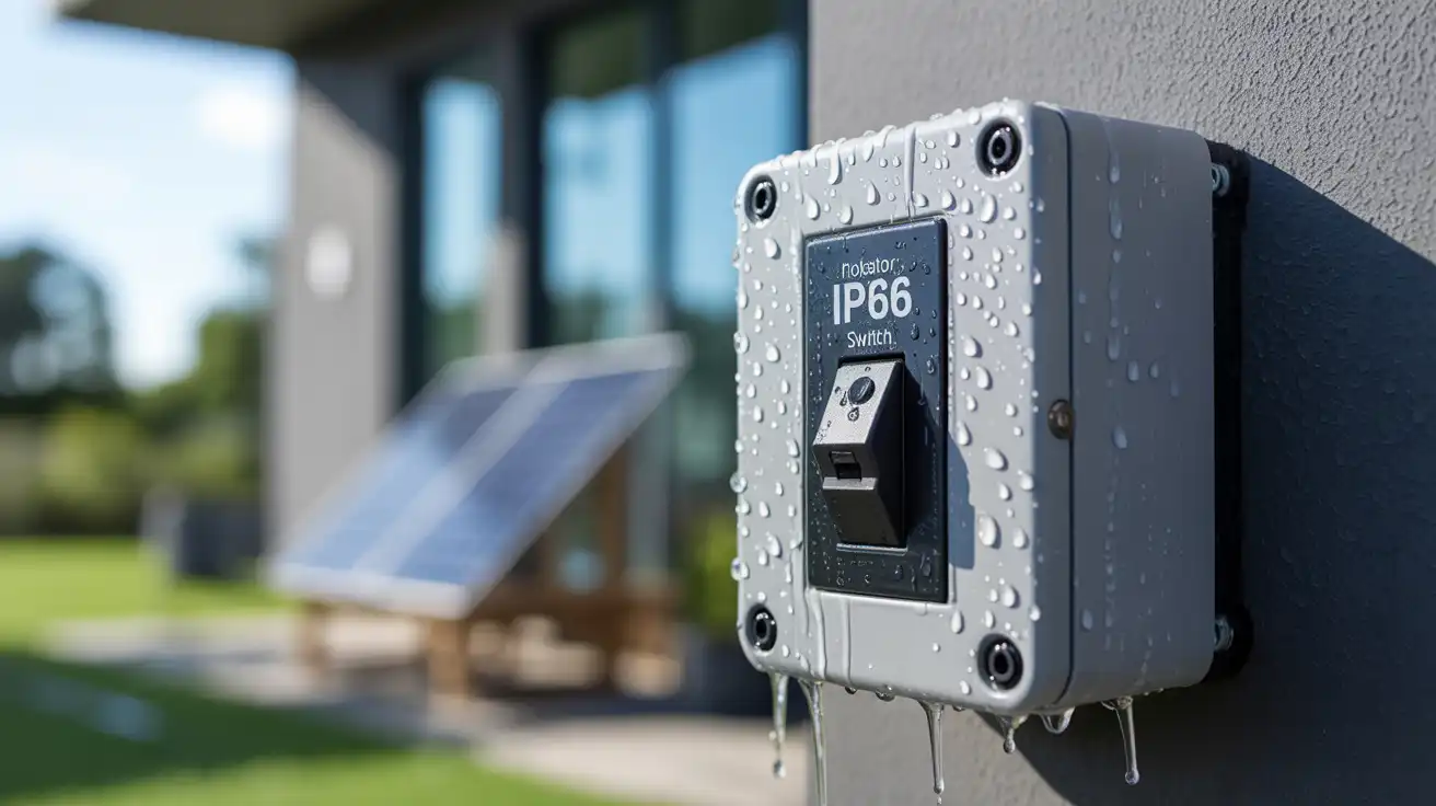
آؤٹ ڈور آئسولیٹر سوئچز کے لیے آئی پی ریٹنگز کے لیے ایک گائیڈ
22 جولائی 2025
واٹر پروف آئسولیٹر سوئچ کا انتخاب کرتے وقت، سمجھنے کے لیے سب سے اہم چیزوں میں سے ایک IP کی درجہ بندی ہے۔ یہ دو حرفی، دو ہندسوں کے کوڈز آپ کو بتاتے ہیں کہ ایک الگ تھلگ سوئچ پانی، دھول اور دیگر بیرونی عناصر سے کتنی اچھی طرح سے حفاظت کرتا ہے — اور یہ بہت اہمیت رکھتا ہے جب آلہ باہر استعمال ہوتا ہے۔ ہیرو پروڈکٹ ہائی لائٹ الیکٹریکل سپلائی ہول سیلر ایک بھروسہ مند الیکٹریکل سپلائی ہول سیلر سے برقی مصنوعات کی مکمل رینج دریافت کریں۔ TOSUNlux عالمی منڈیوں کے لیے سرکٹ بریکر، رابطہ کار، سوئچز اور بہت کچھ پیش کرتا ہے۔ پروڈکٹ دیکھیں اگر آپ اپنی رہائشی، تجارتی یا صنعتی جگہ کے لیے ویدر پروف آئسولیٹ سوئچ خرید رہے ہیں، تو IP ریٹنگز کو سمجھنا آپ کو مہنگی خرابیوں سے بچنے اور طویل مدتی حفاظت کو بہتر بنانے میں مدد کرتا ہے۔ اس آرٹیکل میں، ہم اس بات کو توڑیں گے کہ IP ریٹنگز کا کیا مطلب ہے، اپنی درخواست کے لیے صحیح کو کیسے چنیں، اور TOSUNlux کے IP65 آئیسولیٹر سوئچز سخت ماحول کے لیے ایک قابل اعتماد انتخاب کیوں ہیں۔ آئی پی کی درجہ بندی کیا ہے؟ کوڈ آئی پی کو توڑنے کا مطلب ہے "انگریس پروٹیکشن"، اور اس کی تعریف IEC 60529 کے تحت کی گئی ہے - یہ ایک بین الاقوامی معیار ہے کہ کس طرح انکلوژرز برقی آلات کو غیر ملکی اداروں جیسے دھول اور نمی سے بچاتے ہیں۔ ایک آئی پی ریٹنگ دو نمبروں پر مشتمل ہوتی ہے: مثال کے طور پر: مختصراً: ویدر پروف آئسولیٹنگ سوئچ کے لیے آپ کو کس آئی پی ریٹنگ کی ضرورت ہے؟ صحیح آؤٹ ڈور آئسولیٹر سوئچ کا انتخاب آپ کے استعمال کے معاملے پر منحصر ہے — کیا یہ رہائشی، تجارتی یا صنعتی ہے؟ کیا یونٹ کو بارش، دھول کے طوفان، یا نمی کا سامنا کرنا پڑے گا؟ یہاں ایک فوری خرابی ہے: حفاظت کے لیے، زیادہ تر آؤٹ ڈور سیٹنگز کے لیے IP65 آئیسولیٹر سوئچز یا اس سے زیادہ کا انتخاب کرنے کی سفارش کی جاتی ہے۔ یہ تیز بارش اور گردوغبار دونوں سے تحفظ کو یقینی بناتا ہے […]
مزید پڑھیں