The Complete Guide to Bridge Rectifier – Construction, Working, Advantages
Table of Contents
ToggleToday, most electrical devices feature a semiconductor diode bridge as the transformer that transforms AC input from an electrical source into a DC output that powers its circuitry and components. These discrete electronic parts are commonly referred to as rectifiers and can be found in everything from motor controllers and home appliances to welding applications.
What is a Bridge Rectifier
A bridge rectifier converts alternating current into direct current and can be utilized in many applications, such as switch mode power supplies and linear power supplies. Furthermore, bridge rectifiers may be found in devices like electric welding equipment or radios.
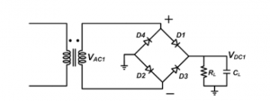
A typical bridge rectifier circuit consists of an input AC voltage, four diodes, and a load resistor connected to the output DC signal’s positive terminal. As shown in Figure 1, this reduces the output voltage by decreasing the current flowing through each diode as shown.
The maximum efficiency of a bridge rectifier is determined by the ratio between DC output power and AC input power. It can reach as high as 81.2%, though, in reality, this figure tends to be much lower due to voltage drops due to current flowing through diodes.
Constructing a Bridge Rectifier
A full wave rectifier is an efficient DC converter that utilizes four diodes in a bridge circuit to convert alternating current (AC) into direct current (DC). The primary benefit of this type of circuit is that it doesn’t need an expensive center-tapped transformer, thus reducing both its size and cost significantly.
When an AC signal is applied to a bridge rectifier, diodes D1 and D3 become forward-biased, while diodes D2 and D4 become reverse-biased. This causes load current to flow through diodes D2 and D3, leading to resistance RL at the output load resistor.
On a negative half cycle, diodes D2 and D3 become forward-biased while C and D4 become reverse-biased. This causes current to flow through diodes C and D to the output RL.
Bridge rectifier output voltages are pulse-like, so to obtain a smooth DC supply, we must filter it with a capacitor. The capacitor charges until the rectified voltage reaches its peak, then discharges into the load circuit when it goes low to smooth out the waveform of rectification.
Types of Bridge Rectifiers
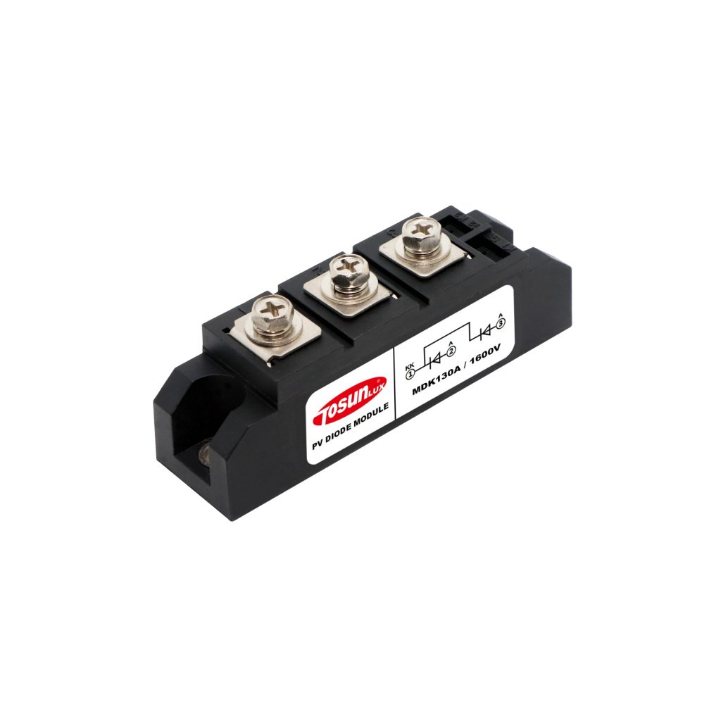
Bridge Rectifiers are semiconductor module products that convert AC input to DC output, which can be used for powering devices. They’re commonly found in workplace appliances and electrical items.
1. Single-Phase
A Single Phase Bridge Rectifier is a widely used rectifier circuit used in applications such as switch mode power supplies and linear power supplies. It utilizes four diodes (D1, D2, D3, and D4) along with a load resistor (RL) to efficiently convert AC into DC.
The rectification process is dependent on the polarity of an input AC waveform. When the positive half cycle appears in this signal, diodes D1 and D3 become forward biased while diodes D2 and D4 become reverse biased. As a result, current begins flowing through D3’s and D4’s short-circuited path.
2. Three-Phase
Used to convert three-phase AC voltage into DC, this device consists of six diodes and provides a cost-effective solution for rectifying the AC power supply into DC without needing a center tap transformer.
Three-phase rectifiers offer greater rectification efficiency compared to single-phase rectifiers, as their output current is lower and fewer AC component is required for dc output.
The three-phase Bridge rectifier is a popular solution for converting AC power into steady DC output, but it requires costly heat sinks and active cooling solutions, which add to its size and complexity.
3. Variable-Phase
Variable Phase Bridge Rectifiers (VPBRs) are electric power converters that transform AC input voltage to DC output voltage. They’re commonly found in systems operating at high frequencies, like aircraft.
These circuits have many applications, such as powering motors, electric drives, lighting, and other electronics. The rectification circuit in these devices is usually constructed using diodes.
Applications of a Bridge Rectifier
A bridge rectifier has many applications in electronic AC power devices like home appliances, motor controllers, modulation processes, and welding processes.
A bridge rectifier is an efficient configuration of four diodes designed to convert AC into DC efficiently. The primary benefit of using a bridge rectifier is that there’s no need for a center-tapped transformer, thus reducing device size and cost.
Bridge rectifiers operate by passing AC voltage through them on both positive and negative half cycles. This causes current to flow across a load resistor RL in similar amounts during these two cycles, producing DC voltage at terminals D and C.
Working Principles of a Bridge Rectifier
A bridge rectifier circuit consists of four diodes, D1, D2, D3, and a load resistor RL connected between terminals A and B. This configuration effectively converts AC (Direct Current) signals without needing an exclusive centered-tapped transformer.
When an input AC signal is applied across a bridge rectifier, terminal A becomes positive, and terminal B becomes negative during a one-half cycle. As such, diodes D1 and D3 become forward-biased, while diodes D2 and D4 become reverse-biased.
On both positive and negative half cycles, the same amount of current flows through the load resistor RL. Therefore, regardless of which way the AC signal was applied, the output DC signal always has the same polarity.
Advantages and Disadvantages of a Bridge Rectifier
A bridge rectifier is a circuit that converts AC to DC. It consists of four diodes and a load resistor.
- Efficiency
It provides a smoother and more reliable output than the half-wave rectifier and can be employed in the modulation of radio signals or electric welding to generate polarized DC voltage.
- Ripple Factor
The ripple factor, or the amount of AC components present in a rectified output from a Bridge Rectifier, should be kept as low as possible. The most efficient way to reduce this number is through the use of filter capacitors which filter out non-sinusoidal waveforms.
- Peak Inverse Voltage
Bridge rectifiers produce double the peak inverse voltage of a center-tapped full-wave rectifier, eliminating the need for an additional center-tap transformer. Furthermore, their output has higher transformer utilization factors than center-tapped full-wave rectifiers, making them more suitable for many applications. However, their pulsating nature may pose risks to sensitive electronic equipment.
- Cost
One of the advantages of this type of rectifier is that it does not need a center-tapped transformer, thus reducing both the cost and size of the device. However, this type of rectifier also has some disadvantages. For instance, power loss with this rectifier is much higher compared to a half-wave rectifier or center-tapped full-wave rectifier.
TOSUNlux low voltage electrical products are a variety of devices designed for use with lower voltage power sources. These include lights, doorbells, garage door openers, and more – all designed to help save you money on energy bills while also improving the aesthetic appeal of your house.
Tel: +86-577-88671000
E-mail: ceo@tosun.com
Skype: tosunelectric
Wechat: +86-139 6881 9286
WhatsApp: +86-139 0587 7291
Address: Room No.1001 Wenzhou Fortune Center,Station Road, Wenzhou, China
REQUEST A QUOTE
WhatsApp us
 : +86-139 0587 7291
 English
 Español
 Русский
 Français
 العربية
 Português do Brasil
 Українська
 Türkçe
 Polski
 Nederlands
 Italiano
 Bahasa Indonesia
 हिन्दी
 اردو
اردو አማርኛ
አማርኛ Հայերեն
 ไทย
ไทย Монгол
 فارسی
فارسی Shqip
Shqip Ελληνικά


