Blog

  • How to Connect Wire to Circuit Breaker: 10 Steps

    12th Feb 2025

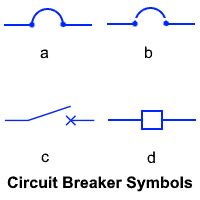
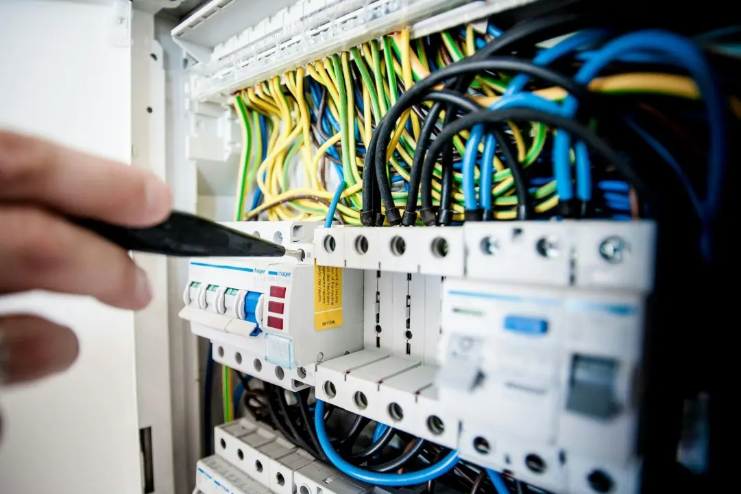
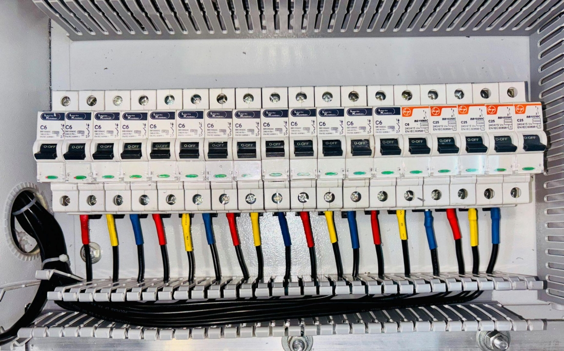
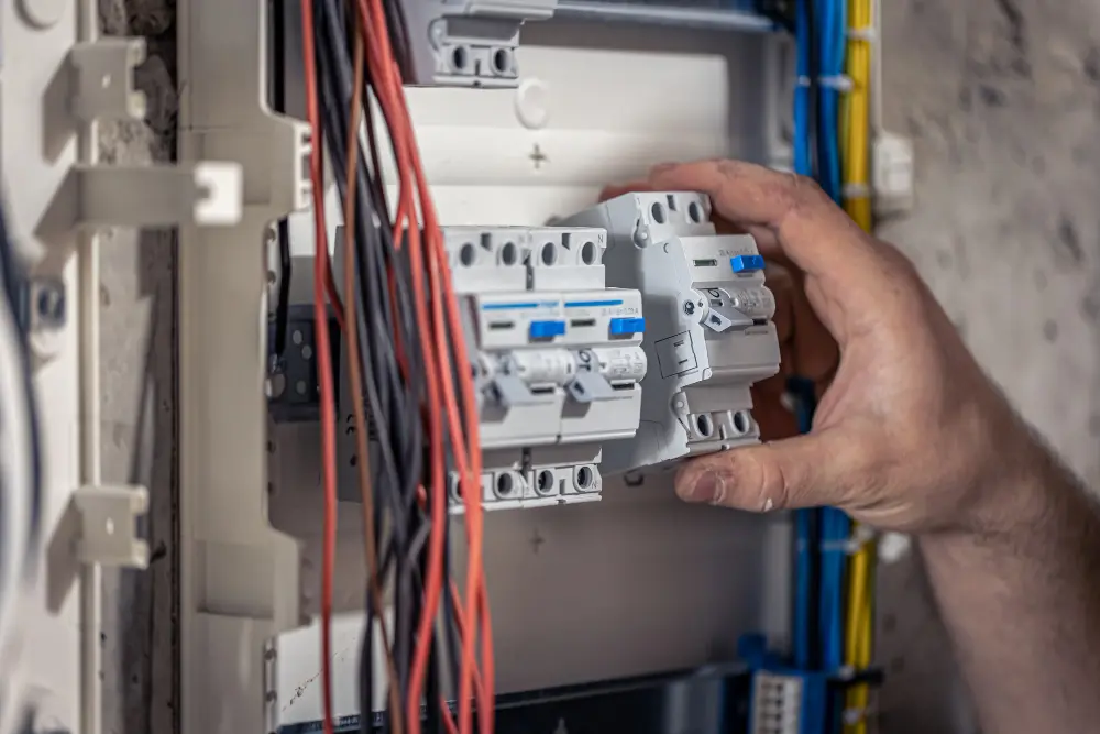
    Connecting a wire to a circuit breaker requires careful handling to ensure safety and proper electrical function.  The process involves selecting the right breaker, preparing the wires, and securing them into the breaker panel correctly.  Whether you’re installing a 20-amp breaker, setting up a 240V circuit breaker, or replacing an old one, following the correct steps is crucial for preventing electrical hazards. This guide will walk you through the 10 essential steps to safely complete a circuit breaker connection while adhering to electrical codes. Understanding Circuit Breaker Connection Basics Before diving into the installation, it’s essential to understand how a circuit breaker panel wiring system works. Circuit breakers control the flow of electricity in a circuit and trip when an overload or short circuit occurs. A single-pole breaker (120V) connects to one hot wire, while a double-pole breaker (240V) connects to two hot wires. The neutral wire (white) returns current to the panel, and the ground wire (green/bare copper) provides a safety path for excess electricity. Having this basic knowledge will make it easier to follow the installation steps. Tools & Materials Needed Before starting, gather these tools and materials: ✔ Circuit breaker (correct amperage, e.g., 20A, 30A, or 50A)✔ Screwdrivers (flat-head and Phillips)✔ Wire strippers✔ Needle-nose pliers✔ Voltage tester✔ Electrical tape✔ Wire nuts (if splicing wires)✔ Correct gauge wire (12 AWG for a 20-amp breaker installation, 10 AWG for a 30A breaker, and 6 AWG for a 50A breaker) Once you have these tools ready, you can move on to the actual wiring process. […]

    Read More
  • Difference Between Double Pole and Single Pole Breaker: Simplified

    11th Feb 2025

    The key difference between a double pole and a single pole breaker is that a single pole breaker controls one 120V circuit, while a double pole breaker controls a 240V circuit by connecting to two hot wires.  Double pole breakers handle more power and are used for larger appliances, while single pole breakers are used for standard household outlets and lights. Read on to learn more. Single Pole vs Double Pole Breaker: Quick Comparison Table Feature Single Pole Breaker Double Pole Breaker Voltage Rating 120V 240V Number of Hot Wires 1 2 Amp Rating Commonly 15-20A Commonly 20-50A Usage Lights, outlets Water heaters, dryers, HVAC units Breaker Width 1 slot in the panel 2 slots in the panel Trip Mechanism Trips when one wire overloads Trips when either wire overloads How Does a Single Pole Breaker Work? A single pole breaker is a circuit breaker that connects to one hot wire and one neutral wire, delivering 120V power.  It trips when there is an overload or short circuit, cutting off power to the affected circuit.  These breakers are commonly rated at 15 to 20 amps and are used for standard home electrical outlets, lighting, and small appliances. Common Applications of Single Pole Breakers Indoor and outdoor lighting circuits Standard electrical outlets in living rooms and bedrooms Small appliances like TVs, coffee makers, and microwaves 120V circuit breakers in home electrical panels How Does a Double Pole Breaker Work? A double pole breaker connects to two hot wires, providing 240V power. It trips when there is […]

    Read More
  • How to Tell If a Circuit Breaker Is Bad: Essential Warning Signs

    07th Feb 2025

    Did you know that faulty electrical systems are a leading cause of home fires? Understanding how to tell if a circuit breaker is bad is crucial for preventing such hazards. This comprehensive guide will help you identify warning signs of a malfunctioning circuit breaker, such as frequent tripping, burning smells, and poor appliance performance. You’ll learn about the lifespan of circuit breakers, the importance of regular maintenance, and when to call a professional electrician. Whether you’re experiencing flickering lights or curious about preventative upgrades, this article covers all your electrical needs to keep your home safe and efficient. Dive in to ensure your home’s electrical system is functioning at its best! Common Indicators of a Faulty Circuit Breaker Understanding the signs of a faulty circuit breaker is crucial for keeping your home safe and your electrical system efficient. Here are some clear indicators that your circuit breaker might be having issues: Frequent Tripping If your circuit breaker keeps turning off, it might be a sign of a problem. Frequent tripping happens when too much electricity is used on one circuit or there’s an internal fault. If this occurs more than three times a month, it’s best to call a licensed electrician to diagnose the issue. You might need to upgrade the breaker or adjust how your electrical load is distributed. Visible Damage Check your circuit breaker for visible damage such as scorch marks, melted wires, or heat on the walls and outlets. These are clear signs of serious internal issues that need immediate attention. Ignoring […]

    Read More
  • How to Choose a Surge Protector

    13th Jan 2025

    When choosing surge protectors, understand your needs and consider factors like joule ratings, clamping voltage, and certifications.  A well-chosen surge protector is a small investment that provides invaluable protection for your electronics and peace of mind. Without them, sudden voltage spikes can destroy sensitive devices, causing costly repairs or replacements.  This article provides a clear guide to help you select the best power surge protector, ensuring your home or office remains protected. 7 Steps on How to Choose a Surge Protector Whether you’re protecting a high-end home theater system or basic household electronics, the right surge protector can save you from costly repairs.  Here’s a step-by-step guide to help you make an informed decision. Step 1: Assess Your Needs Begin by determining the type and number of devices you want to protect.  Are you safeguarding a single device, such as a computer, or do you need comprehensive protection for an entire home setup? Single Device Protection: A basic plug-in surge protector will suffice for individual devices like a laptop or TV. Multiple Devices: Opt for a surge protector with multiple outlets, USB ports, and higher joule ratings. Whole-House Protection: For maximum security, consider a whole-house surge protector to guard your entire electrical system. Step 2: Understand Joule Ratings The joule rating of a surge protector indicates how much energy it can absorb before failing. Higher ratings mean better protection and longer lifespan. Basic Electronics: 600–1,000 joules. Mid-Range Devices: 1,000–2,000 joules. High-End Electronics: 3,000+ joules. Step 3: Check the Clamping Voltage Clamping voltage refers to the […]

    Read More
  • What is the Symbol for Circuit Breakers?

    13th Jan 2025

    Circuit breaker symbols are essential tools for understanding electrical diagrams. They represent various types of circuit breakers and ensure safe, efficient system design.  Knowing these symbols helps professionals identify, install, and troubleshoot components with precision. Read on to learn what these symbols are and how to identify them. What is a Circuit Breaker Symbol? Circuit breaker symbols are standardized graphical representations used in electrical schematics to denote circuit breakers.  These symbols provide a universal language for engineers, electricians, and technicians, allowing them to interpret diagrams accurately and work safely. The symbols convey information about the type, size, and function of circuit breakers, ensuring compatibility and proper usage within the system.  They also play a vital role in maintaining compliance with safety standards like the International Electrotechnical Commission (IEC) and the American National Standards Institute (ANSI). Understanding these symbols is critical for anyone working with electrical systems, as they help prevent errors, reduce downtime, and promote safety. Key Types of Circuit Breaker Symbols Credits to: ElectricalTechnology a. MCB Circuit Breaker Symbol Miniature Circuit Breakers (MCBs) are commonly used in residential and small commercial applications to protect against overcurrent and short circuits.  The symbol for an MCB typically consists of a rectangle with a break in the middle, indicating the breaker’s ability to interrupt the flow of electricity. MCBs are widely appreciated for their compact size, ease of installation, and reliable protection. Understanding their symbol is essential for professionals working on smaller electrical systems. b. MCCB Symbol Molded Case Circuit Breakers (MCCBs) are designed for higher current […]

    Read More
  • How Does a Current Transformer Work?

    12th Jan 2025

    A current transformer (CT) protects equipment from overloads, ensures system reliability, and provides accurate data for analysis. It is a crucial component in electrical systems, stepping down high currents to manageable levels for safe measurement and control.  In this article, we explore CTs’ design, operation, and applications while comparing types, connections, and maintenance tips to help you better understand their role in power systems. What is a Current Transformer? A current transformer measures high currents by stepping them down to safer values.  Unlike power transformers, CTs are used primarily for monitoring and protection, feeding scaled-down current to meters and relays.  These devices are essential for maintaining system safety, enabling precise readings even in high-power environments. How Does a Current Transformer Work? Current transformers operate on electromagnetic induction. The primary winding carries the system’s current, generating a magnetic field in the core.  This induces a proportional current in the secondary winding.  For example, if a CT has a 100:5 ratio, a 100-ampere current in the primary will produce a 5-ampere current in the secondary. The stepped-down current is relayed to meters, relays, or control devices for monitoring and protection.  CTs ensure accuracy and safety by isolating the high-current system from sensitive measuring instruments. Current Transformer Construction The construction of a CT ensures durability and precision. Key components include: Core: Made from high-permeability material (e.g., silicon steel) to maximize magnetic flux and reduce energy loss. Primary Winding: Carries the high current from the system. Often a single turn or system conductor. Secondary Winding: Steps down the current […]

    Read More
  • How to Test a Circuit Breaker and Applicable Methods to Try

    12th Jan 2025

    Key steps in testing circuit breakers include visual inspections for signs of damage, using a test button to simulate faults, and conducting detailed tests with tools like a multimeter or voltage tester.  These methods help identify potential issues early, ensuring your circuit breaker operates reliably and prevents system failures. By conducting regular inspections, you can detect potential faults early, preventing hazards like electrical fires or system failures.  This guide covers essential steps, from identifying a bad breaker to using advanced testing methods, ensuring your system runs smoothly and safely. Why Circuit Breaker Testing is Important Circuit breakers are essential for safeguarding electrical systems against overcurrent and short-circuit hazards. Over time, wear and tear, environmental factors, or manufacturing defects can compromise their functionality. Testing helps detect these issues early, reducing the risk of electrical malfunctions that could damage equipment, cause downtime, or pose serious safety risks.  Moreover, routine testing extends the lifespan of both circuit breakers and the overall electrical system by ensuring optimal performance.  Neglecting this practice could lead to costly repairs or replacements, making circuit breaker inspection an essential part of any maintenance routine. How to Tell if a Circuit Breaker Is Bad A faulty circuit breaker can lead to various electrical issues, but identifying the problem early can save time and money.  Here’s how to determine if your breaker is bad: Signs of a Bad Circuit Breaker Frequent tripping under normal load conditions. Visible scorch marks or discoloration on the breaker. A burning smell is coming from the breaker box. The breaker feels […]

    Read More
  • What is the Interrupt Capacity of a Circuit Breaker?

    11th Jan 2025

    The interrupt capacity of a circuit breaker is its ability to safely disconnect a faulted circuit by interrupting a short circuit or overload current.  This rating is essential for selecting the right breaker for a system, ensuring safety, and preventing damage.  Understanding interrupt ratings helps avoid catastrophic failures by matching breakers with fault current levels specific to an electrical installation. What is Interrupt Capacity? Interrupt capacity refers to the maximum amount of fault current that a circuit breaker can safely interrupt without being damaged or posing a hazard to the electrical system.  When a short circuit or overload occurs, the breaker’s primary function is to isolate the faulty circuit from the system.  If the fault current exceeds the breaker’s interrupt capacity, the breaker may fail to open properly, leading to dangerous conditions like electrical fires or equipment damage. This rating is typically expressed in kiloamperes (kA) and is a crucial factor when selecting circuit breakers.  A breaker with a higher interrupt capacity is designed to handle more substantial fault currents.  For example, a breaker rated at 10 kA can safely interrupt fault currents up to 10,000 amperes.  Choosing a breaker with an appropriate interrupt capacity ensures that, during a fault, the breaker will trip quickly to protect the system, reducing the risk of damage or fire. What Determines a Circuit’s Capacity? A circuit’s capacity refers to the amount of current it can handle safely without overheating or suffering permanent damage.  Several factors determine a circuit’s capacity, including conductor size, system voltage, breaker type, and overall […]

    Read More
  • Understanding Transformers: What is the Difference Between CT and PT?

    10th Jan 2025

    The primary difference between current transformers (CTs) and potential transformers (PTs) lies in their function: CTs measure and step down high current levels, while PTs measure and reduce high voltage levels for safe and accurate monitoring.  Both play vital roles in electrical systems, ensuring the safety and reliability of power distribution.  This article explores their distinct purposes, construction, and applications to provide a clear understanding of their differences. CT vs PT: Key Differences Overview Feature Current Transformer (CT) Potential Transformer (PT) Measurement Focus Current measurement Voltage measurement Input Range High current (e.g., 100A to 5,000A) High voltage (e.g., 11kV to 400kV) Output Range Low, safe current (e.g., 5A or 1A) Standardized low voltage (e.g., 110V) Common Uses Industrial and substation current monitoring Power transmission voltage monitoring Accuracy High for current at varying loads High for voltage at fixed ratios Key Differences Between CT and PT Primary Function CTs measure current by stepping down high current levels, while PTs measure voltage by reducing high voltage to a safer level. Design and Construction CTs are built to handle high currents, often featuring a toroidal design. PTs, in contrast, are designed for precise voltage scaling, with insulation suited for high-voltage applications. Accuracy and Load Handling CTs are optimized for current accuracy under varying load conditions. PTs prioritize voltage precision to ensure accurate metering and relay operation. Applications CTs are ideal for industrial systems requiring current monitoring, while PTs are essential for transmission and distribution systems requiring voltage control. What is a Current Transformer (CT)? A current transformer (CT) […]

    Read More
  • What Does RCD Stand For​?

    10th Jan 2025

    RCD stands for Residual Current Device, which is used as a component in electrical safety systems.  It quickly shuts off electricity when it detects a current imbalance, protecting people from electric shocks and preventing fire risks.  Whether in homes or commercial setups, RCD installation is vital to safeguard lives and property. What Is an RCD? An RCD monitors the flow of current through live and neutral wires and trips the circuit if it detects a leakage current, typically caused by a fault or accidental contact.  RCDs are essential in protecting users and preventing electrical fires, making them a standard feature in modern electrical installations. How Does an RCD Work? RCDs operate by continuously measuring the current flow in both live and neutral conductors.  Under normal conditions, the current remains balanced. If there’s a difference—indicating leakage to the ground—the RCD disconnects the circuit within milliseconds.  This rapid response minimizes the risk of electric shocks and reduces the chances of electrical fires. What Causes an RCD to Trip? RCDs trip when they detect a current imbalance, but several factors can trigger this response: Faulty Appliances: Damaged or aging appliances can cause current leakage, leading to tripping. Wiring Issues: Loose or damaged wires may leak current, prompting the RCD to activate. Moisture or Water Ingress: In wet areas like bathrooms, even minor moisture exposure can cause the RCD to trip. Overloading: While not the primary function of an RCD, circuit overloading may sometimes lead to tripping if combined with a leakage fault. Regular inspection and testing ensure that […]

    Read More
Loading...