Blog

  • Pros and Cons of Electric Busbar

    06th Mar 2025

    Electric busbars are efficient and known as compact solutions for transmitting electricity in electrical power distribution systems.  They replace traditional wiring methods, improving system reliability and organization.  However, like any electrical component, busbars come with both advantages and limitations that must be considered before installation. This article explores what you need to know about the advantages and drawbacks of electric busbars. Read on to learn more. What is a Electrical BusBar? An electric busbar is a metallic strip or bar that conducts electricity within a power distribution system.  Typically made of copper or aluminum, busbars serve as centralized hubs for power transmission, allowing multiple circuits to branch off efficiently.  They are commonly used in switchgear, substations, and distribution panels to streamline electrical connectivity and reduce wiring complexity. How Does a Busbar System Work? A busbar system consists of conductors that distribute electricity between incoming and outgoing feeders.  It acts as a common connection point where electrical currents can be directed from power sources to different circuits.  The system is designed to handle high voltage loads safely and effectively, often integrating insulation and protective enclosures to prevent electrical faults. Pros of Electric Busbars 1. Space Efficiency and Compact Design Unlike traditional cabling, busbars require significantly less space.  Their compact design allows for easier installation in high-density electrical panels, making them ideal for applications where space is limited. 2. Enhanced Electrical Efficiency Busbars minimize resistance and power loss, improving overall electrical efficiency.  They allow for better heat dissipation, reducing energy waste and the risk of overheating compared […]

    Read More
  • What is the Function of a Thermal Overload Relay?

    05th Mar 2025

    A motor thermal overload relay is a protective device that prevents electric motors from overheating by detecting excessive current flow and disconnecting power when necessary.  This ensures the motor runs safely and efficiently while reducing the risk of damage. Understanding Thermal Overload Relays A motor thermal overload relay is a crucial component in electrical systems, particularly in motor protection.  It works by monitoring the current flowing through a motor and reacting when the current exceeds safe limits for a prolonged period.  This device prevents overheating, prolongs motor life, and minimizes electrical hazards. How a Thermal Overload Relay Works The relay consists of bimetallic strips that bend when exposed to excessive heat caused by high current.  When the bending reaches a certain point, the relay trips, cutting off power to the motor and preventing further overheating.  Once the temperature normalizes, the relay resets automatically or manually. Thermal Overload Relay Symbol Credits to Siemens Key Features of Thermal Overload Relays Current Sensing Mechanism – Detects excessive current and activates protection. Adjustable Settings – Allows users to set overload limits based on motor specifications. Auto/Manual Reset Options – Provides flexibility in restoring motor function. Trip Indicators – Displays a signal when the relay has tripped. Compatibility with A Overload Contactor – Works alongside motor starters for complete protection. Importance of Thermal Overload Protection Motor thermal overload protection is essential for ensuring motor longevity and electrical safety.  Without it, motors can suffer from: Overheating – Leading to insulation damage and component failure. Excessive Energy Consumption – Causing inefficiency and […]

    Read More
  • Breaking Capacity vs. Circuit Breaker Ratings: Are They The Same?

    04th Mar 2025

    Breaking capacity and circuit breaker ratings are often confused, but they serve different purposes in electrical systems.  Breaking capacity refers to the maximum fault that can safely interrupt, while circuit breaker ratings cover multiple specifications like voltage, current, and interrupting capacity of circuit breakers.  Selecting the correct breaker requires an understanding of both.  In this guide, we’ll break down their differences and why both are critical for electrical safety. Key Differences Between Breaking Capacity and Circuit Breaker Ratings Aspect Circuit Breaker Ratings Breaking Capacity Definition The complete set of electrical specifications of a breaker. The maximum fault current is the one the breaker can safely interrupt. Unit of Measurement Amperes (A) for current, Volts (V) for voltage. Kiloamperes (kA) for short-circuit current. Purpose Defines how a breaker operates under normal conditions. Determines the breaker’s ability to handle fault conditions. Importance Ensures correct sizing and protection for circuits. Prevents damage during short circuits and ensures system safety. Understanding these differences helps in selecting the right circuit breaker for any electrical application. Understanding Circuit Breaker Ratings A circuit breaker rating is a set of electrical parameters that determine how a breaker operates under normal and fault conditions. These ratings ensure that a breaker functions effectively within its designed limits. The key specifications include: Rated Current (In) This is the continuous current a breaker can carry without tripping. It is measured in amperes (A) and typically ranges from 1A to several thousand amperes, depending on the breaker type. Rated Voltage (Ue) This defines the maximum system voltage at […]

    Read More
  • Simple Guidelines For Circuit Breaker Repair

    14th Feb 2025

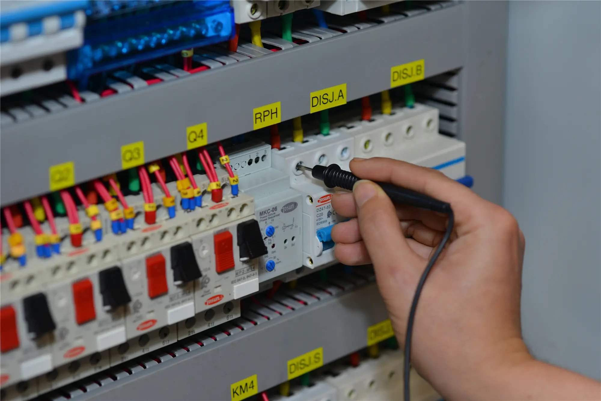
    Circuit breaker repair ensures a safe and functional electrical system by fixing or replacing faulty breakers.  If a circuit breaker is broken, it may cause power loss, overheating, or fire hazards.  Knowing how to fix a circuit breaker or change a circuit breaker helps prevent electrical failures and ensures safety. Read on to learn more. How to Identify a Faulty Circuit Breaker Before performing a circuit breaker repair, confirm if the breaker is actually faulty. Signs of a bad breaker include: Frequent Tripping – If the breaker trips even under normal load, it may be worn out. No Power Restoration – If resetting the breaker doesn’t restore power, it could be defective. Physical Damage – Burn marks, melted plastic, or a burning smell indicate internal failure. Loose or Stiff Handle – If the switch is difficult to move or won’t stay in place, the breaker mechanism may be damaged. Steps to Fix a Circuit Breaker Step 1. Turn Off the Power and Ensure Safety Shut off the main breaker to prevent electrical shock. Use a voltage tester to confirm no electricity is flowing before working on the panel. Step 2. Inspect the Breaker and Load Check for loose connections, burn marks, or overheated wiring. Sometimes, the issue isn’t the breaker but an overloaded circuit or faulty appliance. Step 3. Reset or Replace the Breaker Try resetting the breaker by flipping it fully OFF, then back ON. If it immediately trips again or won’t reset, you may need to replace the circuit breaker. How Do I […]

    Read More
  • What’s the Application of Solid State Relay?

    14th Feb 2025

    Solid-state relays (SSRs) are used in industrial automation, HVAC systems, medical devices, and consumer electronics for fast, reliable, and silent switching.  Unlike mechanical relays, SSRs operate without moving parts, making them more durable and efficient. Read on to learn more about them. What is a Solid-State Relay (SSR)? A solid-state relay (SSR) is an electronic switching device that controls electrical power without mechanical contact.  Instead of using physical moving parts, it relies on semiconductor components like thyristors, TRIACs, or MOSFETs to switch circuits on and off.  This design eliminates wear and tear, providing longer service life and faster operation compared to traditional mechanical relays. How Does a Solid-State Relay Work? An SSR is an electronic switching device that controls power flow using semiconductor components instead of physical contacts.  It operates by receiving a low-voltage control signal, activating an internal optocoupler, and triggering a switching element like a TRIAC or MOSFET.  This process allows for high-speed, arc-free switching. 7 Applications of Solid-State Relays #1. Industrial Automation SSRs play a key role in factory automation, controlling motors, heating elements, and high-power machinery.  Their fast switching speed and ability to handle frequent operations make them ideal for programmable logic controllers (PLCs) and robotic systems. #2. HVAC and Temperature Control Heating, ventilation, and air conditioning (HVAC) systems use SSRs for precise temperature regulation.  They are often used in thermostats, ovens, and industrial furnaces where precise and noise-free switching improves performance. #3. Medical Equipment In medical devices like diagnostic machines and laboratory instruments, SSRs provide reliable and silent operation.  Their […]

    Read More
  • What Type of Circuit Breaker Do I Need?

    14th Feb 2025

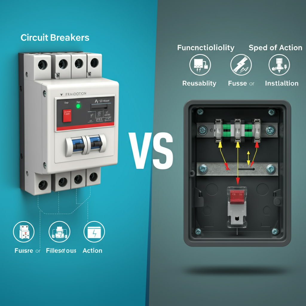
    The right circuit breaker depends on your electrical system’s voltage, current, and application.  Standard circuit breakers work for residential use, while commercial and industrial setups require breakers with higher interrupting capacities.  Identifying the correct breaker involves considering its class, size, and compatibility with your electrical panel. So, if you’re looking for the best circuit breakers at home, this article is made just for you. Read on to learn more. Understanding Circuit Breakers A circuit breaker is an essential safety device that protects electrical circuits from overcurrents, short circuits, and ground faults.  When excessive current flows through the circuit, the breaker trips, stopping the electrical supply to prevent damage, fires, or electrocution.  Unlike fuses, which need to be replaced after a fault, circuit breakers can be reset and reused. Selecting the correct circuit breaker ensures system reliability, reduces the risk of electrical hazards, and complies with electrical codes.  Various factors, including breaker type, size, and application, influence the best choice for a given system. How to Identify the Right Circuit Breaker Choosing the right circuit breaker involves several considerations. Here’s what you should check: #1. Voltage & Current Rating The circuit breaker must match your system’s voltage and current capacity. Residential systems typically use 120V for small circuits and 240V for large appliances. Commercial and industrial setups may require breakers rated for 480V or higher to handle high-power equipment. #2. Panel Compatibility The breaker must fit your electrical panel’s brand and model. Some breaker brands are not interchangeable, so always check compatibility. #3. Breaker Class & […]

    Read More
  • Parts of a Circuit Breaker: How Do They Work?

    13th Feb 2025

    A circuit breaker is an essential safety device that automatically stops electrical flow when an overload, short circuit, or fault occurs.  It prevents electrical fires, equipment damage, and electrocution.  The key parts of a circuit breaker—such as the contacts, trip unit, and arc extinguisher—work together to detect faults and interrupt the current safely. In this article, we’ll break down the circuit breaker components, explain their functions, and explore the purpose of a circuit breaker in residential, commercial, and industrial applications. Definition of Circuit Breaker in Physics In physics and electrical engineering, a circuit breaker is a switching device that can open and close a circuit manually or automatically under normal and abnormal conditions.  Unlike fuses, which must be replaced after tripping, circuit breakers can be reset and reused multiple times. Circuit breakers are widely used in power systems, industrial plants, and household electrical panels to ensure electrical safety and system reliability. Main Components of a Circuit Breaker A circuit breaker consists of several key components, each playing a crucial role in detecting and interrupting faulty currents. #1. Frame (Body/Enclosure) The frame or housing is the outer shell of the breaker, providing mechanical support and insulation. It: Protects internal components from dust, moisture, and physical damage. Provides dielectric insulation to prevent electrical leakage. Houses various parts such as the operating mechanism and trip unit. Frames are typically made from high-strength plastic or molded case materials in low-voltage breakers, while industrial circuit breakers use metal-clad enclosures for extra durability. #2. Contacts (Fixed and Moving Contacts) Contacts are […]

    Read More
  • Residential Circuit Breakers vs Industrial Circuit Breakers

    12th Feb 2025

    Residential circuit breakers are designed for home electrical systems, while industrial circuit breakers handle higher voltages, currents, and harsher conditions in commercial and manufacturing environments. Choosing which type suits your needs is crucial — whether you’re looking for circuit breaker manufacturers or for personal uses. Read on to learn more. Residential Circuit Breakers vs Industrial Circuit Breakers: Quick Comparison Table Feature Residential Circuit Breakers Industrial Circuit Breakers Voltage Rating 120V / 240V 480V / 600V and above Current Rating 15A – 200A 200A – 5000A Usage Homes, small offices Factories, power plants, commercial buildings Durability Moderate High, built for harsh conditions Breaker Type MCBs, MCCBs MCCBs, ACBs, VCBs Interrupting Capacity 10kA – 22kA 25kA – 150kA Key Differences Between Residential and Industrial Circuit Breakers #1. Voltage and Current Ratings Residential breakers handle 120V/240V circuits with lower amperage, typically between 15A and 200A.  These ratings are sufficient for household electrical systems, powering everyday appliances, and lighting.  Industrial breakers, on the other hand, operate at much higher voltages, usually 480V/600V and above, and can manage currents up to 5000A, making them essential for heavy-duty applications. #2. Interrupting Capacity The interrupting capacity of residential circuit breakers ranges from 10kA to 22kA, which is adequate for preventing electrical hazards in homes.  Industrial circuit breakers have a much higher interrupting capacity, typically between 25kA and 150kA, allowing them to safely handle large fault currents in commercial and industrial settings where power demands are significantly greater. #3. Durability and Build Quality Residential breakers are built for moderate conditions, as they are […]

    Read More
  • How to Connect Wire to Circuit Breaker: 10 Steps

    12th Feb 2025

    Connecting a wire to a circuit breaker requires careful handling to ensure safety and proper electrical function.  The process involves selecting the right breaker, preparing the wires, and securing them into the breaker panel correctly.  Whether you’re installing a 20-amp breaker, setting up a 240V circuit breaker, or replacing an old one, following the correct steps is crucial for preventing electrical hazards. This guide will walk you through the 10 essential steps to safely complete a circuit breaker connection while adhering to electrical codes. Understanding Circuit Breaker Connection Basics Before diving into the installation, it’s essential to understand how a circuit breaker panel wiring system works. Circuit breakers control the flow of electricity in a circuit and trip when an overload or short circuit occurs. A single-pole breaker (120V) connects to one hot wire, while a double-pole breaker (240V) connects to two hot wires. The neutral wire (white) returns current to the panel, and the ground wire (green/bare copper) provides a safety path for excess electricity. Having this basic knowledge will make it easier to follow the installation steps. Tools & Materials Needed Before starting, gather these tools and materials: ✔ Circuit breaker (correct amperage, e.g., 20A, 30A, or 50A)✔ Screwdrivers (flat-head and Phillips)✔ Wire strippers✔ Needle-nose pliers✔ Voltage tester✔ Electrical tape✔ Wire nuts (if splicing wires)✔ Correct gauge wire (12 AWG for a 20-amp breaker installation, 10 AWG for a 30A breaker, and 6 AWG for a 50A breaker) Once you have these tools ready, you can move on to the actual wiring process. […]

    Read More
  • Difference Between Double Pole and Single Pole Breaker: Simplified

    11th Feb 2025

    The key difference between a double pole and a single pole breaker is that a single pole breaker controls one 120V circuit, while a double pole breaker controls a 240V circuit by connecting to two hot wires.  Double pole breakers handle more power and are used for larger appliances, while single pole breakers are used for standard household outlets and lights. Read on to learn more. Single Pole vs Double Pole Breaker: Quick Comparison Table Feature Single Pole Breaker Double Pole Breaker Voltage Rating 120V 240V Number of Hot Wires 1 2 Amp Rating Commonly 15-20A Commonly 20-50A Usage Lights, outlets Water heaters, dryers, HVAC units Breaker Width 1 slot in the panel 2 slots in the panel Trip Mechanism Trips when one wire overloads Trips when either wire overloads How Does a Single Pole Breaker Work? A single pole breaker is a circuit breaker that connects to one hot wire and one neutral wire, delivering 120V power.  It trips when there is an overload or short circuit, cutting off power to the affected circuit.  These breakers are commonly rated at 15 to 20 amps and are used for standard home electrical outlets, lighting, and small appliances. Common Applications of Single Pole Breakers Indoor and outdoor lighting circuits Standard electrical outlets in living rooms and bedrooms Small appliances like TVs, coffee makers, and microwaves 120V circuit breakers in home electrical panels How Does a Double Pole Breaker Work? A double pole breaker connects to two hot wires, providing 240V power. It trips when there is […]

    Read More
Loading...