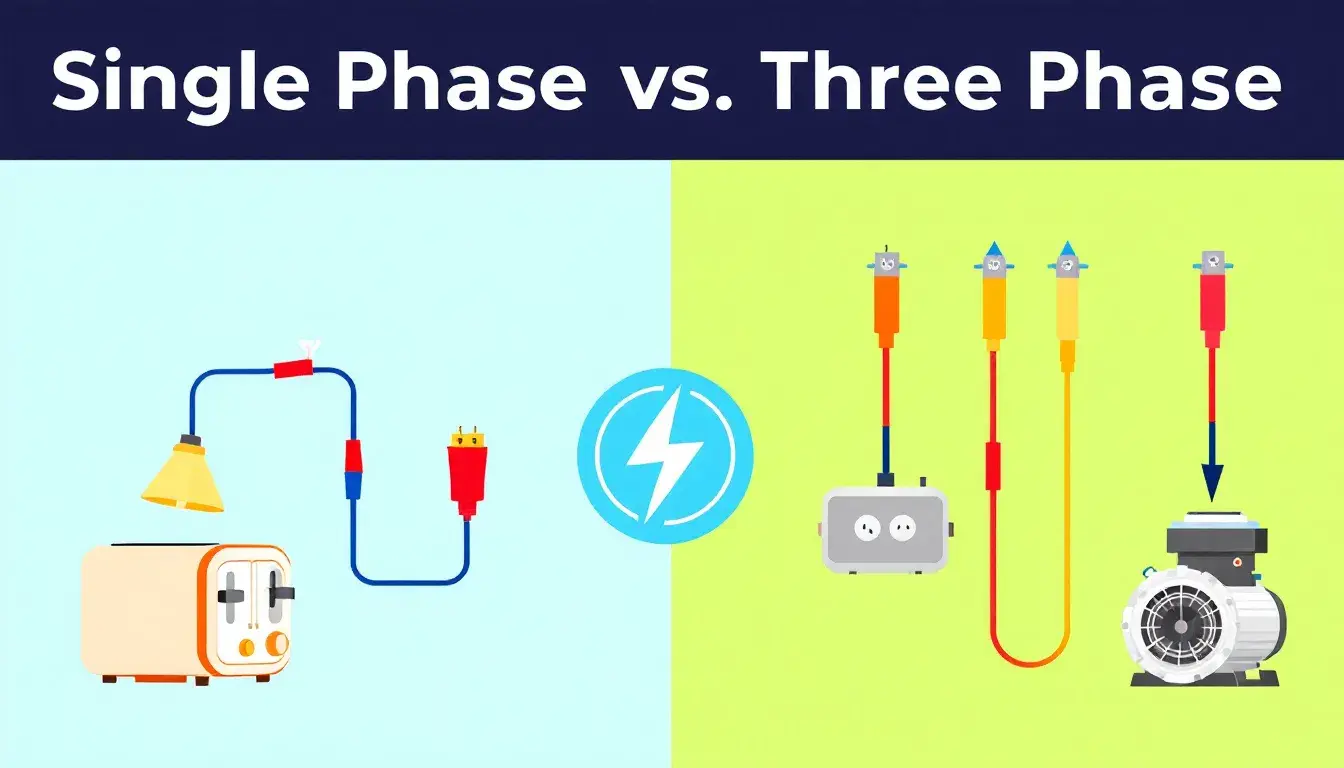
Single Phase vs Three Phase Electricity: Which is Best for You?
23rd Mar 2025
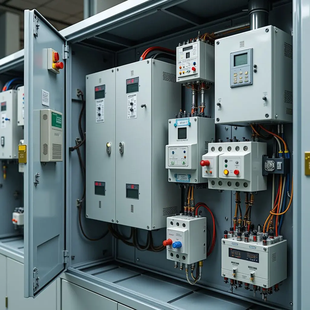
Choosing between single phase vs three phase electricity depends on your power needs. This article compares the two, explaining their differences, advantages, and best uses. Key Takeaways Single-phase power suits residential applications with simpler design and maintenance capabilities, handling loads up to 2,500 Watts efficiently. Three-phase power enables continuous and stable power delivery, making it ideal for industrial and commercial applications that require higher loads and efficiency. Understanding the differences between single-phase and three-phase power is crucial for selecting the appropriate system based on specific energy needs, particularly in energy-intensive environments like data centers. Understanding Single Phase Power Single-phase power is a basic component of electrical systems, consisting of a two-wire alternating current circuit with a phase wire and a neutral wire. The current alternates direction 50 to 60 times per second (AC), typically at a voltage of 230V and a frequency of 50 Hertz, making it ideal for household applications like lighting and heating. Single-phase power is crucial in daily life due to its straightforward design, making it perfect for residential areas with low electrical power demand. Household appliances such as lights, refrigerators, and small heating systems depend on it, ensuring smooth and efficient home operations. Advantages of Single Phase Power Single-phase power offers several advantages, including simpler design and installation compared to three-phase systems, making it cost-effective for residential use. This simplicity also means easier maintenance and troubleshooting, benefiting homeowners and small businesses. Single-phase power supplies are ideal for residential supplies, handling capacities up to 2,500 Watts. This is sufficient for common household […]
Read More
 : +86-139 0587 7291
 English
 Español
 Русский
 Français
 العربية
 Português do Brasil
 Українська
 Türkçe
 Polski
 Nederlands
 Italiano
 Bahasa Indonesia
 हिन्दी
 اردو
اردو አማርኛ
አማርኛ Հայերեն
 ไทย
ไทย Монгол
 فارسی
فارسی Shqip
Shqip Ελληνικά