Blog

  • Fused Disconnect Switch vs Circuit Breaker

    21st Apr 2024

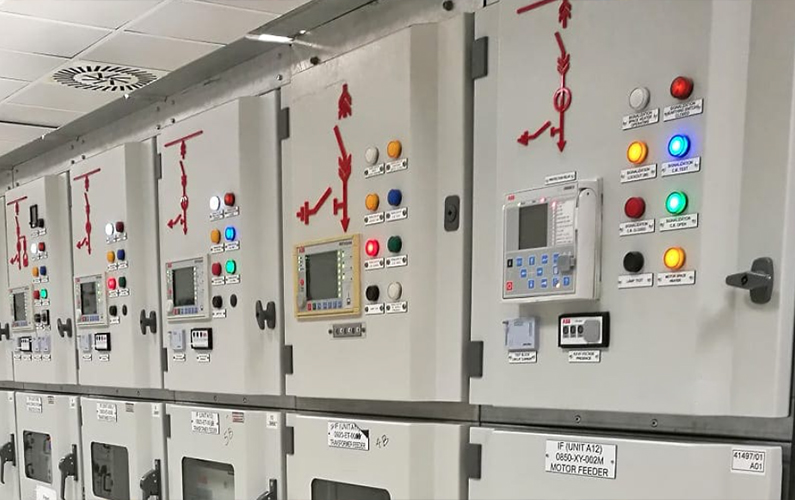
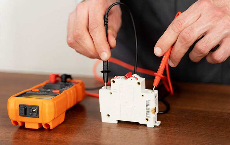
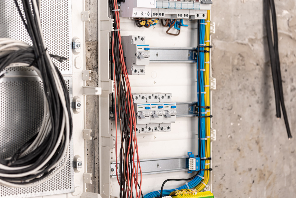
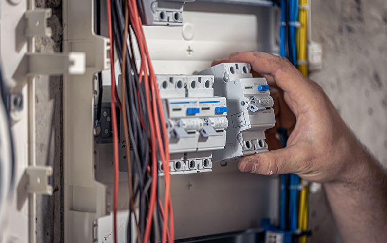
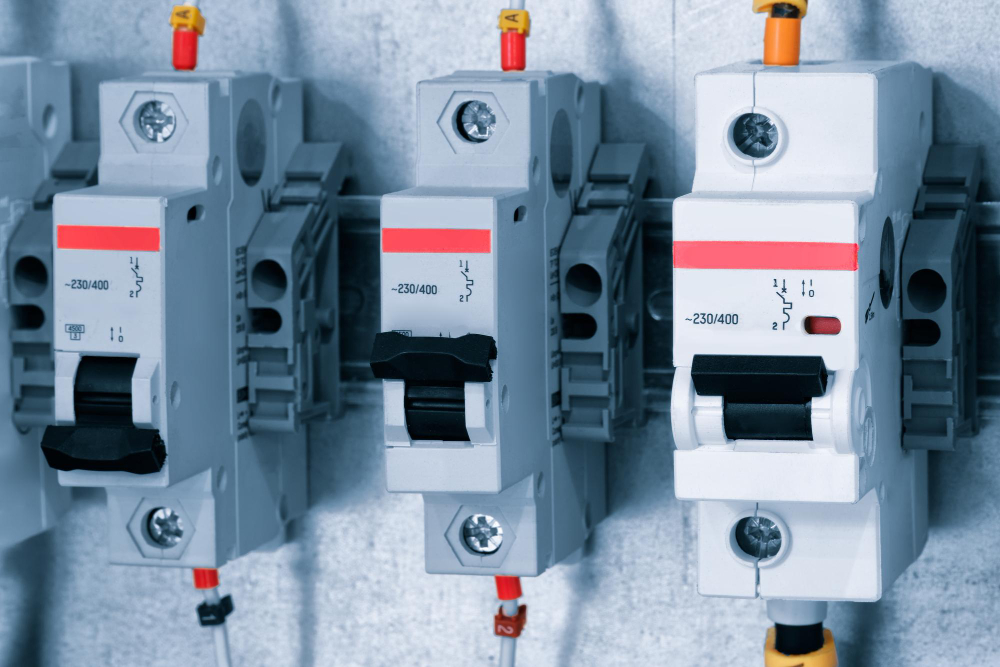
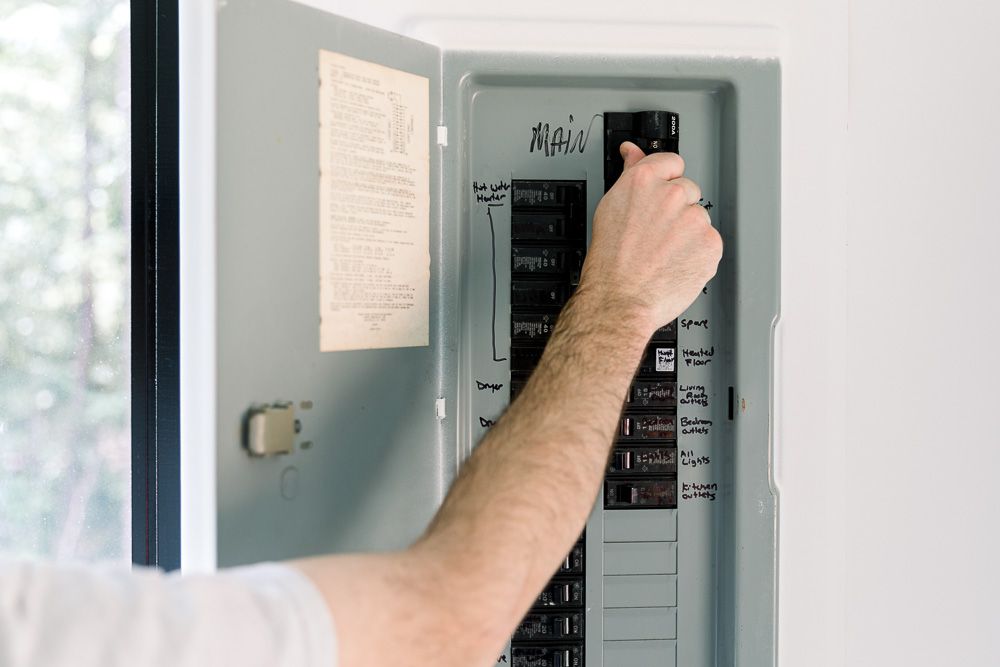
    Overload protection comes in two main forms – fused disconnect switches and circuit breakers. Both open overloaded circuits, but have distinct ways of detecting issues and interrupting current flow.  Fused switches rely on melted fuse elements to open circuits Circuit breakers have internal bimetal trip mechanisms Fuses allow very fast clearing in high-current situations Understanding a few key variances helps select the best choice. What is a Fused Disconnect Switch? A fused disconnect switch combines a manually-operated knife switch with one or more fixed current-rated fuses wired in series. During normal operation, contacts remain closed and allow unimpeded current flow to downstream equipment. No action occurs until an overload or short circuit event heats fuse elements beyond their capacity. At this point, the conductive metal literally melts and visually opens the circuit with certainty. Fused switches then require replacement of blown fuse elements before re-closing contacts. No resetting exists as with breakers – just replacement. Related Reading: What is a Fuse Switch Disconnector? What is a Circuit Breaker? A circuit breaker relies on an internal bimetal strip that predictably deforms under sustained overcurrent heat. The bimetal bending eventually releases a latch and trips open contacts to stop current flow.  After cooling and manually toggling the handle off/on, the breaker can resume normal operation without replacement parts. This resettability contrasts with fused switches. Fused Disconnect Switch vs Circuit Breaker – Key Differences Here are a few key differences between the two variations: Clearing Severe Overloads Thanks to the very fast melting of calibrated fuse elements, fused […]

    Read More
  • What’s the Difference Between Protection Relays vs Control Relays?

    19th Apr 2024

    Relays are electromagnetic devices that open or close electrical contacts to control circuits. But within this broad category, protection and control relays serve very distinct purposes. Both protection relays and control relays play important roles in electrical systems, but they serve very different purposes. Their differing functions and capabilities drive design tradeoffs to consider. Control relays amplify signals to switch loads Protection relays safeguard equipment Operating speed is critical for protection relays Their differing roles and capabilities drive design tradeoffs that engineers must consider for various applications. What is a Control Relay? Control relays switch electrical loads on and off based on input signals, allowing low power circuits to activate higher powered lights, horns, valves, motors, and more.  Their primary functions are signal amplification through contact multiplication and overload protection for delicate switching electronics. Popular examples include starter, timer, latching, and automotive relays. What is a Protection Relay? Protection relays safeguard electrical infrastructure and equipment from excessive currents, voltages, temperatures, frequencies, etc.  They continuously monitor system conditions and quickly engage circuit breakers or send shutdown signals when thresholds are exceeded. Common types include overcurrent, differential, distance, transformer, generator, and arc-flash protection relays. Protection Relays vs Control Relays – Key Differences  Here are a few key differences between protection relays and control relays: Operating Speed Control relays may switch loads on and off frequently, as fast as multiple times per second. Their electromechanical contacts must withstand this high-duty cycle operation over years of hot switching. But operating speed is less critical – 10 to 50 milliseconds […]

    Read More
  • Selection and Installation Guide to Control Relays

    16th Apr 2024

    Control relays provide invaluable signal switching and amplification in industrial control panels. Selecting the right relay models for an application and properly installing them determines reliability. Consider these key factors and best practices. Choose relay electrical ratings to suit loads Ensure adequate clearance for heat dissipation Use socket mounts for easy replacement Employ interface modules for sensor compatibility Control relays may seem simple, but choosing incorrectly can lead to premature failure. Whereas overlooking proper installation procedures can produce loose connections and noise-prone circuits. With critical processes at stake, carefully select and mount relays. Related Reading: A Complete Guide to Control Relays Control Relays – Factors to Consider Here are a few things to keep in mind while investing your money in control relays: Electrical Load Considerations Consider voltage, current draw, and switching capacity of loads the relays will control. Standard control relays operate from 5 to 240V AC/DC and switch up to 15 amp residential loads or 6 amp inductive. For heavier industrial loads, contactors can handle up to 600V and 200A. Use narrow voltage bands for AC relays to prevent hum and chatter. Check motor start surge currents fall within relay specs if directly switching inductive loads. And allow a safety margin below published contact ratings – 20-30% for resistive loads, 50% for motors. Mechanical Design Factors Consider the mechanical life expectancy of relays in continuous switching applications like conveyor belts or pumps. Standard life expectancies range from 100,000-500,000 cycles. But more durable 10-20 million cycle relay contacts suit highly repetitive automation tasks. Also, […]

    Read More
  • How To Wire a Control Relay?

    14th Apr 2024

    Control relays provide a simple yet invaluable way to switch electrical loads in automation systems. But properly wiring them requires adhering to terminal layout standards and sound connection practices. Understanding basic relay pinouts and terminations ensures reliable performance. Standard 4 and 5-pin terminal configurations Connect trigger circuit to coil terminals Output load wires attach to NO/NC contacts Employ good wiring practices at terminals While relays ease system designs, miswired connections can lead to all kinds of functional issues or even equipment damage. By following proper wiring procedures, electricians can avoid common mistakes. Common Relay Terminal Configurations The most widespread relay terminal structure features a 5-pin inline layout. Two pins connect to the triggering coil, while the other three connect to individual switch contacts – normally open (NO), normally closed (NC), and common. Inside, the coil actuates the contact armature when energized. 4-pin relays simply omit the normally closed terminal, while the NO and common pins remain. This compact format works for simpler on/off load control instead of maintaining separate offline circuits. But the operating principle stays identical. Step-by-Step Wiring Instructions Here’s a brief step-by-step guide on how to wire a control relay: Determine Relay Type and Contacts First, confirm whether you need a single-pole, single-throw (SPST) or single-pole, double-throw (SPDT) relay. This determines available contact terminals. Also, decide if the load should stay normally open or normally closed when the relay coil is de-energized per your control scheme. This ensures proper operation when triggered. Choose Wire Gauge for Amperage Consult automotive amp charts to specify […]

    Read More
  • How to Install an RCCB?

    12th Apr 2024

    Residual current circuit breakers (RCCBs) are indispensable for modern electrical safety. RCCBs constantly monitor current flow and instantly disconnect circuits if leakage is detected. While electricians routinely handle RCCB installation, handy homeowners can also learn this useful skill. Here are the key steps involved. Always de-energize panels before wiring RCCBs Load side wires connect outwards to protected circuits Test tripping response before re-energizing Faulty RCCBs endanger rather than protect Let’s get into the details on how to install an RCCB! RCCBs – An Overview RCCBs (or RCDs) protect against electric shock by detecting even small leakage currents to ground. Unlike standard breakers, RCCBs trip well below the amperage levels that can seriously harm humans. When installed correctly, they provide an invaluable extra security layer. While seeming complex, RCCBs are relatively straightforward to mount and connect like a normal breaker. Homeowners comfortable working inside electrical panels can handle most residential RCCB installations.  Installing an RCCB – Step-by-Step Guide Here is a simplified overview of the process. Power Off for Safety Before touching any wiring inside an electrical service panel, always fully disconnect the main breaker or switch fuse cutting all power. Verify the panel and targeted RCCB mounting location is completely de-energized using a non-contact voltage tester. Electrocution hazards are extreme without this first critical safety step. Identify the Load Side Study the intended circuit’s wiring to distinguish the “line” side that connects to the main supply from the “load” side that runs power out to lights, receptacles and devices. RCCBs are mounted on the load […]

    Read More
  • The Difference Between ELCBs and RCCBs

    11th Apr 2024

    Electrical safety devices like ELCBs and RCCBs constantly monitor circuits and rapidly disconnect power when faults occur. But while serving similar purposes, these two technologies work quite differently. Understanding key differences in detection methods, fault types addressed, and breaker capabilities clarifies optimal applications. ELCBs solely detect earth faults, and RCCBs find all leakage RCCBs cover more fault types but can nuisance trip ELCBs suit high-current circuits, RCCBs for full protection ELCBs and RCCBs both provide vital shock prevention. But RCCBs now supersede older electromechanical ELCB designs in most new builds due to wider fault coverage. Here’s how these two residual current devices compare. What is an ELCB? The original earth leakage circuit breaker (ELCB) detects current flow imbalances between hot and neutral supply conductors. This identifies earth faults when higher current returns on neutral back to the panel. Their electromechanical coils trigger fast mechanical relay trips in the milliamp range when imbalance thresholds are crossed. However, ELCBs have no “residual” fault detection beyond simple hot/neutral measurements. More advanced RCCBs now outpace ELCBs in performance and precision. What is an RCCB? As the name implies, residual current circuit breakers (RCCBs) detect leakage current diverting from hot to ground rather than neutral returns. This provides fuller coverage and faster response down to 30 milliamps of ground fault, whereas ELCBs often only trip at 100 milliamps or more. RCCBs use compact electronic detection coils rather than mechanical coils and relays for precision fault identification. When any stray leakage current is sensed, the breaker trips in under 40 milliseconds. […]

    Read More
  • RCBO vs RCCB: Key Differences Explained

    10th Apr 2024

    Upgrading electrical safety means choosing between RCCBs for pure shock prevention and RCBOs with added overcurrent stops. While their names sound alike, these technologies provide overlapping yet distinct protection. How do RCCBs and RCBOs differ in form and function? RCCBs solely detect leakage faults, and RCBOs have overcurrent RCBOs combine RCCB and MCB circuits in one body RCCBs maximize safety, RCBOs add circuit breaker capabilities RCCBs identify leakage currents for fast shutoff against shocks. RCBOs build in standard circuit protection, too. Selecting the right device starts with understanding their capabilities. What are RCCBs and How Do They Work? The term RCCB stands for residual current circuit breaker. RCCBs work by constantly sampling electrical current in the hot and neutral lines to detect any deviations or “residual” leaking to the ground. This identifies ground faults that indicate potential shock risks. Once a RCCB senses stray current exceeding 30 milliamps, its control circuit trips the breaker in under 40 milliseconds – much faster than a human body can withstand a shock. This makes dedicated RCCBs ideal for power points and wet areas needing maximum safety. What are RCBOs and How Do They Function? By contrast, a residual current circuit breaker with overcurrent protection (RCBO) combines ground fault detection like an RCCB while also integrating standard circuit breaker overcurrent capabilities in a single body. The RCCB portion samples current flow to catch leakage faults. Circuit breaker components additionally monitor the line current level and will trip at a preset amperage threshold in case of overloads and short circuits. […]

    Read More
  • Do All Houses Have The Main Breaker?

    21st Feb 2024

    If you’re not familiar with the main breaker, it is a device that controls the flow of electricity through a house. Usually, the breaker is located in the middle of a circuit panel. The breaker controls the flow of 120 volts of electricity. The main breaker interrupts this flow before the branch breakers can work. Most houses have one of these devices, but not all. You can find your main circuit breaker on the outside of your home or in the main electrical panel. There are only a few houses that don’t have a main breaker, but they’re a common sight. Most houses have at least one 100-amp breaker, though some might have two or more. You can check with your building maintenance staff to be sure.  A subpanel gets its power from the main panel. Its amp rating must match the main panel circuit’s. The number of subpanels is limited to the number of main breaker panel circuits. If you need to add more power to your house, you should call your local utility company and/or an electrician.  If you want to know whether all houses have a main breaker, continue reading this article.  What Is the Main Breaker? A circuit breaker is a device that automatically trips when a circuit becomes overloaded, which can lead to fires or even electrocution. Circuit breakers are designed to detect and stop overloaded circuits. They can also be triggered by power surges.  Before you tackle electrical repairs, you should know what the main breaker is. This device […]

    Read More
  • When Would You Use An Automatic Transfer Switch?

    19th Feb 2024

    Automatic transfer switches are important for a few reasons. First, they make power outages easier. Then, when there’s a problem with your electricity, you don’t have to worry about manually switching over to an alternate power source.  When you have a backup power supply, you can simply set the automatic transfer switch to automatically start the generator if the power goes out. If you don’t need a backup power supply, this switch can save your business. Another reason to install an ATS is to protect against overcurrents. This device is designed to monitor two sources of power and transfer your load to either source. It will switch from one source to the other when it senses that the other power source is no longer safe for your equipment.  If you want to know when to use an automatic transfer switch, continue reading this article.  What is an Automatic Transfer Switch? This is a piece of equipment that automatically transfers electrical energy from one generator to another. While it may sound complicated, automatic transfer switches are fairly easy to use and install.  They feature clearly labelled ports and are relatively inexpensive. Before you buy an automatic switch, though, make sure that it is suitable for your needs. If you’re not sure about its functionality, you can always consult an electrical engineer. The switch allows you to avoid a potential power outage. The transfer mechanism will automatically switch power from one source to another, providing a way to continue power in the event that one source fails.  […]

    Read More
  • The Different Types of MCCB and How It Works

    17th Feb 2024

    There are different types of circuit breakers, and you need to know how they work in order to install them correctly. These circuit breakers are grouped into different types: type B, type C, type D, type K, and type Z. A type B MCCB will trip when it sees a surge of 3 to 5 times the rated current, while a type C will trip when it sees a surge 5 to 10 times. An MCCB is an excellent electrical protection device. Its casing is sealed and cannot be opened. But just like any other electrical equipment, it requires periodic maintenance in order to function properly.  MCCBs can handle a large current and a short circuit. They also have a movable trip unit and a short tripping time. Some types have remote ON/OFF features, making them useful in industrial settings where electrical shocks are a common hazard. Different types of MCCBs are used in different electrical settings. If you want to know about the different types of MCCBs and how it works, continue reading this article.  How Does an MCCB Work? MCCBs are designed to automatically interrupt the flow of electricity when a fault is detected. They consist of several key components, such as the relay tripping unit, temperature-sensitive components like the bimetallic strip, and arcing contacts. The combination of these features allows the MCCB to respond to overloads and short circuits by rapidly disconnecting the faulty circuit, ensuring electrical safety. Relay Tripping Unit: This is the brain of the MCCB. It includes an electromagnetic […]

    Read More
Loading...