 : +86-139 0587 7291
 English
 Español
 Русский
 Français
 العربية
 Português do Brasil
 Українська
 Türkçe
 Polski
 Nederlands
 Italiano
 Bahasa Indonesia
 हिन्दी
 اردو
اردو አማርኛ
አማርኛ Հայերեն
 ไทย
ไทย Монгол
 فارسی
فارسی Shqip
Shqip Ελληνικά

Everything You Need to Know About Busbars
Table of Contents
ToggleBusbars play a vital yet oft overlooked role in electrical power systems, providing the framework for current to safely and efficiently flow. As facilities look to push their systems to higher capacities with optimized designs, properly specifying busbars proves increasingly important. Their conductivity, flexibility, and protective functions make busbars the true workhorses transmitting lifeblood to electrical rooms.
- Busbars efficiently distribute high currents with minimal resistance and losses
- Configurable designs accommodate changing layouts and component additions
- Protective elements safeguard equipment from faults while enhancing uptime
- Dissipating heat loads protects connections from overheating
Let’s find out everything one should know about busbars:
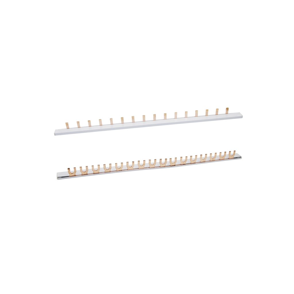
What is a Busbar?
What is a busbar used for? Constructed from highly conductive materials like copper and aluminum, busbars form the direct metallic pathways carrying heavy loads throughout facilities. By offering low impedance compared to cable runs, they allow power to smoothly flow from external feeds and busway entrances to individual circuit breakers and switchgear loads. Copper Busbars effectively minimize voltage drop and maximize load serving capacity.
Conduction and Distribution
Networked in parallel at their connection points, busbars simultaneously feed multiple downstream devices while balancing loads. Uniform current distribution prevents overburdening any single cable or component. Their grid-like topologies further allow flexible rearrangement and future proofing of layout changes with minimal rework.
Connection Flexibility
Busbar systems spare integrators the hassle of running countless individual conductor runs by providing pre-manufactured “plug and play” modular architectures. Strategically placed bolted or clamped joints enable rapid installation and reconfiguration of outgoing circuit configurations with ease.
Design Configurations
Common busbar system varieties include:
Insulated Branch-Circuit Busbars
This cost-effective design separates bus conductors with durable insulation like PVC. It efficiently carries circuit loads in a compact manner while preventing accidental contact.
Air-Insulated Busbars
Prefabricated enclosures contain open-air bus conductors, relying on air gaps rather than solid insulation for separating phases. Easy visualization simplifies maintenance compared to enclosed designs.
Enclosed Bus Ducts
Heavy-gauge aluminum or copper bars run through rigid metal conduits for maximum protection against environmental hazards. Work well in industries with debris-prone or wet-area conditions.
Material Selection
Common busbars are typically made of copper, aluminum, and alloy variations. Key factors driving material choice involve:
- Conductivity – Copper excels but aluminum offers nearly identical performance at lower cost. Alloys balance properties.
- Mechanical Strength – Heavier copper withstands vibrations better while aluminum resists corrosion in many environments.
- Operating Temperatures – Higher conductivity materials like copper transfer heat more efficiently, minimizing derates.
Sizing Considerations
Proper sizing begins by calculating maximum load currents and surging demands. Busbars are rated using ampacities and must accommodate 125-150% of loads to prevent overheating. National Electrical Code further dictates sizing to restrict voltage drops.
Busbar sizing tools simplify this by inputting project details like current type, operating temperatures, ambient conditions and desired safety factors to output optimized dimensional parameters. This lowers design complexities and errors.
Mounting and Joining
Securing an electrical busbar system firmly yet adjustably involves either bolt-on saddles, clamps or threaded standoffs. Low-resistance joints make or break systems – wire-brushing contact surfaces before compressing pre-tinned or antioxidant-treated connections minimizes distributed losses.
Protective Features
Given busbars’ role transmitting massive currents, they incorporate features shielding personnel and equipment from faults:
- Insulation – PVC, epoxy powder, or tape coatings rate at 600V minimum, preventing direct contact.
- Fusing – Generally installed near voltage sources and heavy load-outs, fuses protect wiring should a busbar overload.
- Segmenting – Strategic installation of molded-case or miniature circuit breakers partitions the bus to isolate impacted sections if trip occurs.
- Grounding – A dedicated copper or aluminum grounding bus safely channels stray leakage currents to source.
- Monitoring – Thermal and current sensors detect overload conditions, triggering alarms before damage results.
Bus Transfer Equipment
Automatic or manual bus transfer equipment safely routes power between redundant bus sections. This enables one to be isolated while the other seamlessly handles the full load, facilitating maintenance without downtime.
Bus Duct Options
Prefabricated bus duct fittings allow assembling complete modular busway runs. Popular enclosed metal duct options include:
- Flanged Elbows: Compact radius 90° elbows for tight turns.
- Tees: “Y” branches direct power to additional equipment lines.
- End Sections: Enclosure panels cap and lock busway runs at entry/exit points.
- Hangers/Supports: Various angle brackets and strut channel mounts securely brace runs.
Selecting a reputable full-service busbar manufacturer ensures full project support from conception through commissioning and beyond as needs evolve over time. Their industry expertise streamlines system design and installation.
Installation Best Practices
Proper installation techniques minimize installation time while maximizing busbar service life. Key steps include:
- Mount busbars and supports with corrosion-resistant hardware sized for structural loads and short-circuit forces.
- Maintain NEC clearances between busbars and other live electrical equipment for insulation and ease of maintenance/upgrades.
- Torque all bolted connections firmly as per manufacturer specifications using calibrated torque wrenches to ensure low-resistance joints.
- Inspect for foreign debris trapped between phases before energization and address with compressed air.
- Phase-mark all connections clearly to avoid conflicts during future servicing.
- For large busway runs, start installation from the load end and work back towards the source to prevent miswiring.
- Provide access working space around busbars per code and manufacturer guidelines.
- For underground sections, protect bus ducts further using concrete encasement or metallic conduit.
Adhering to best practices streamlines busbar commissioning and helps facilities avoid maintenance headaches down the road.
Conclusion
As the sturdy backbone routing power throughout mission-critical facilities, proper busbar specification proves key to optimizing electrical performance and long-term resilience. TOSUNLux holds decades of industry experience designing and manufacturing high-quality busbar systems tailored for nearly any application. Contact their engineering experts today to review design requirements and receive customized layout recommendations minimizing downtime and maximize uptime.

Tel: +86-577-88671000
E-mail: ceo@tosun.com
Skype: tosunelectric
Wechat: +86-139 6881 9286
WhatsApp: +86-139 0587 7291
Address: Room No.1001 Wenzhou Fortune Center,Station Road, Wenzhou, China
REQUEST A QUOTE
WhatsApp us