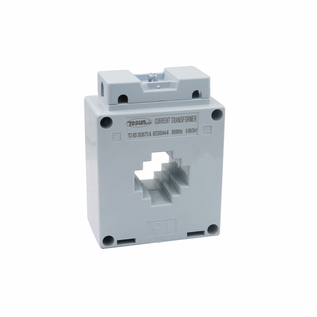
How Does a Current Transformer Work?
Table of Contents
ToggleA current transformer (CT) protects equipment from overloads, ensures system reliability, and provides accurate data for analysis.
It is a crucial component in electrical systems, stepping down high currents to manageable levels for safe measurement and control.
In this article, we explore CTs’ design, operation, and applications while comparing types, connections, and maintenance tips to help you better understand their role in power systems.
What is a Current Transformer?
A current transformer measures high currents by stepping them down to safer values.
Unlike power transformers, CTs are used primarily for monitoring and protection, feeding scaled-down current to meters and relays.
These devices are essential for maintaining system safety, enabling precise readings even in high-power environments.
How Does a Current Transformer Work?
Current transformers operate on electromagnetic induction. The primary winding carries the system’s current, generating a magnetic field in the core.
This induces a proportional current in the secondary winding.
For example, if a CT has a 100:5 ratio, a 100-ampere current in the primary will produce a 5-ampere current in the secondary.
The stepped-down current is relayed to meters, relays, or control devices for monitoring and protection.
CTs ensure accuracy and safety by isolating the high-current system from sensitive measuring instruments.
Current Transformer Construction
The construction of a CT ensures durability and precision. Key components include:
- Core: Made from high-permeability material (e.g., silicon steel) to maximize magnetic flux and reduce energy loss.
- Primary Winding: Carries the high current from the system. Often a single turn or system conductor.
- Secondary Winding: Steps down the current and connects to measuring instruments.
- Insulation System: Prevents short circuits and ensures operator safety.
In some cases, oil or epoxy resin is used to enhance insulation and cooling, particularly for high-voltage CTs.
The robust design ensures accurate current transmission, even in harsh environments.
Current Transformer Design
Design elements of CTs are crucial for accurate and safe operation. Key design aspects include:
- Core Saturation: The core must handle high magnetic flux without saturating, ensuring linear response.
- Accuracy Class: Determines the CT’s measurement precision, classified by the percentage error it allows (e.g., 0.5%, 1%).
- Burden Capacity: Refers to the maximum load (in ohms) the secondary can drive without sacrificing accuracy.
Additionally, modern CTs feature advanced safety mechanisms, such as thermal overload protection and fault isolation, making them reliable for critical applications.
Types of Current Transformers
CTs come in various designs, tailored for specific applications:
| Type | Features |
| Wound Current Transformers | Feature a primary winding wound directly on the core; Ideal for low to moderate current applications, offering precise measurements. |
| Bar-Type Current Transformers | Use the system conductor as the primary winding; Commonly employed in high-current industrial systems. |
| Window (Toroidal) Current Transformers | There is no primary winding; the conductor passes through the core; Widely used in switchgear and control panels due to their compact size and versatility. |
Each type is suited to different scenarios, ensuring flexibility and reliability in power systems.
Current Transformer Connection
Proper connection is crucial for CT performance and safety. Typical configurations include:
- Single-Phase Systems – A single CT measures the current in each phase, ensuring accurate monitoring.
- Three-Phase Systems – Three CTs are used, one for each phase, to monitor total system performance.
Key Considerations for Connections
- Polarity: Correct polarity ensures accurate readings and prevents system malfunctions.
- Grounding: Grounding the secondary side protects against dangerous voltage buildup.
Improper connections can lead to inaccuracies, equipment failure, or even safety hazards.
Current Transformer Ratio
The CT ratio determines the proportional relationship between primary and secondary currents. Below is a summary of typical ratios and their applications:
| Primary Current | Secondary Current | Ratio | Applications |
| 100A | 5A | 20:1 | Residential and small commercial systems |
| 500A | 5A | 100:1 | Industrial power distribution systems |
| 3000A | 1A | 3000:1 | High-voltage substations and grids |
The ratio ensures accurate scaling for safe measurement and monitoring. Choosing the right ratio depends on the system’s current requirements and the intended application.
Advantages of Current Transformers
CTs offer numerous benefits, including:
- Safety: They isolate high currents, protecting instruments and operators.
- Cost-efficiency: They eliminate the need for expensive high-current measuring equipment.
- Accuracy: CTs ensure precise current measurements, which are essential for billing and analysis.
These advantages make CTs indispensable in modern power systems.
Limitations and Challenges
Despite their benefits, CTs face some challenges:
- Core Saturation: This can lead to measurement inaccuracies under extreme currents.
- Burden Impedance: High secondary load affects accuracy.
- Ratio Errors: Deviations in the CT ratio may result in incorrect readings.
Addressing these limitations through proper design, installation, and maintenance is critical.
Applications of Current Transformers
CTs serve various purposes in industries such as:
- Power Distribution: Monitoring and controlling electricity flow.
- Metering: Providing accurate readings for energy consumption and billing.
- Protection Relays: Detecting faults and initiating corrective measures to prevent system damage.
These applications highlight CTs’ versatility and importance in maintaining electrical system stability.
Maintenance Tips for Current Transformers
Proper maintenance ensures longevity and optimal performance. Here are essential tips:
- Regular Inspection: Check for physical damage, overheating, or loose connections.
- Insulation Testing: Use a megohmmeter to measure insulation resistance and prevent breakdowns.
- Calibration: Verify the CT ratio periodically to maintain measurement accuracy.
- Cleaning: Keep the CT and surrounding area free of dust, debris, and moisture to prevent corrosion.
- Oil Testing (for oil-insulated CTs): Analyze the oil for contaminants or signs of degradation to ensure effective insulation and cooling.
Routine maintenance minimizes the risk of failure and extends the CT’s lifespan.
Current Transformermer FAQs
Why are current transformers used in power systems?
CTs provide safe and accurate current measurement, essential for monitoring and protection.
What is the difference between a current transformer and a potential transformer?
CTs measure current, while potential transformers measure voltage.
How do you calculate a current transformer ratio?
Divide the primary current by the secondary current to determine the ratio.
What happens if a current transformer is open-circuited?
It can generate dangerously high secondary voltage, posing a safety risk.
What are the common causes of current transformer failure?
Overheating, insulation breakdown, and mechanical damage are typical culprits.
Current Transformers: Conclusion
Current transformers are indispensable in modern electrical systems, ensuring safe and accurate current measurements.
From their robust construction to their diverse applications, CTs play a vital role in maintaining system stability and protection.
By understanding their design, operation, and maintenance, you can maximize their efficiency and safeguard your electrical infrastructure.
Tel: +86-577-88671000
E-mail: ceo@tosun.com
Skype: tosunelectric
Wechat: +86-139 6881 9286
WhatsApp: +86-139 0587 7291
Address: Room No.1001 Wenzhou Fortune Center,Station Road, Wenzhou, China
REQUEST A QUOTE
WhatsApp us
 : +86-139 0587 7291
 English
 Español
 Русский
 Français
 العربية
 Português do Brasil
 Українська
 Türkçe
 Polski
 Nederlands
 Italiano
 Bahasa Indonesia
 हिन्दी
 اردو
اردو አማርኛ
አማርኛ Հայերեն
 ไทย
ไทย Монгол
 فارسی
فارسی Shqip
Shqip Ελληνικά


